
Repair Instruction
Fault
description:
The
audio is distorted (buzz, growl)
but crystal clear through the earphone jack
This
repair instruction fixes only this problem!
This is a common problem with most SW1
required tools:
small
screwdriver for slotted head screws
soldering iron with small cone, solder
sharp knife, pliers or tweezers
and a slow hand !!
Duration: ca 1 h
Cost: ca. 1 Euro
Components:
2 capacitors 22µF / 16V tantalum
( 10V or 25V also possible - check dimension!)
Optional a 3mm super bright white LED (ca. 1 Euro)

AT YOUR OWN RISK !!!
Open all three screws
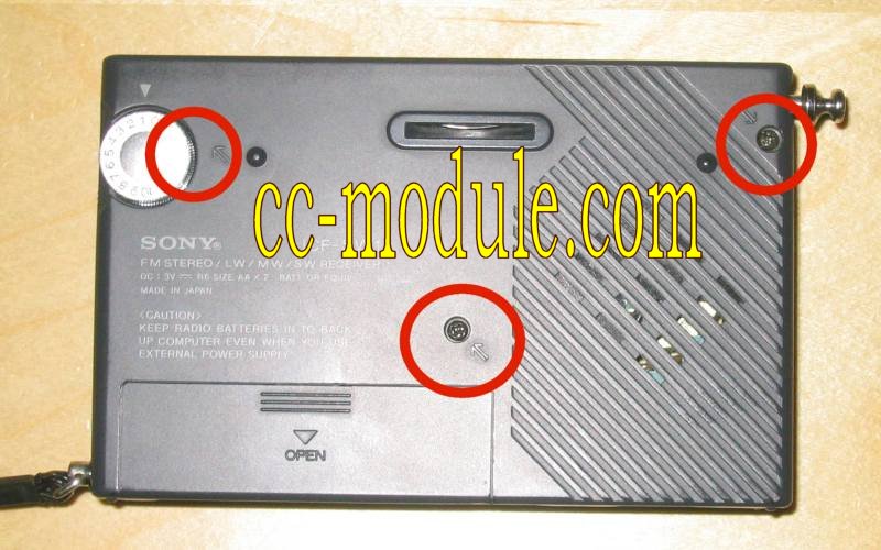
Pull upward the volume control adjuster to find the third screw. Remove the black plastic film.
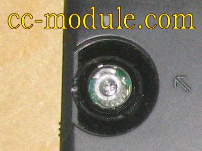
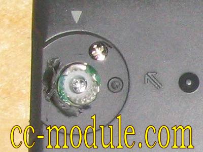
Take
care when you open the casing. Handle the fixations with
care.
Remove
the black cover.
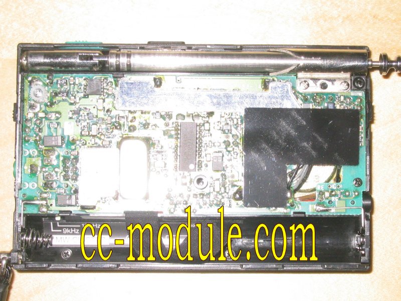
Desolder
the black and grey cables:
"BR" = speeker right connection
"A2" = speeker left connection
Three ground connections on the third soldering point
Dismantle the antenna / aerial
Remove the screws inside the battery case
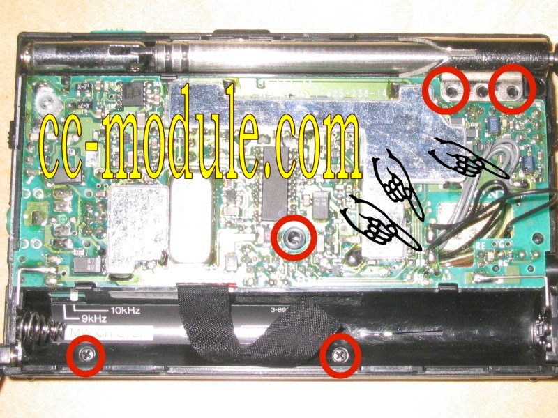
Lift up inner life.
Remove three screws, push upward and fold to the right.
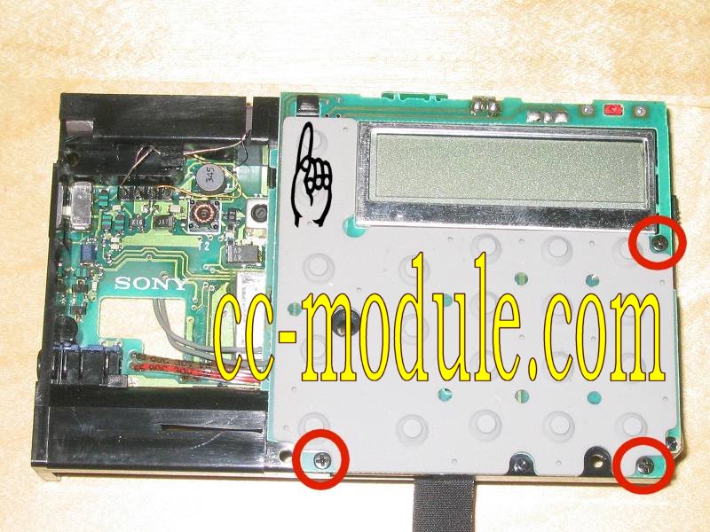
Remove three screws, open the fixation and fold downwards.
Remove the plastic bolt.
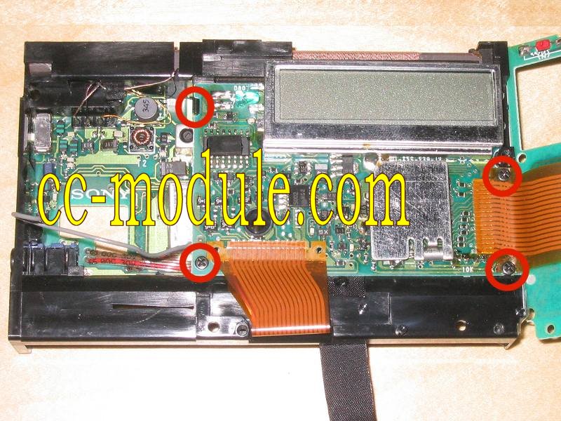
Desolder these two SMD-capacitors.
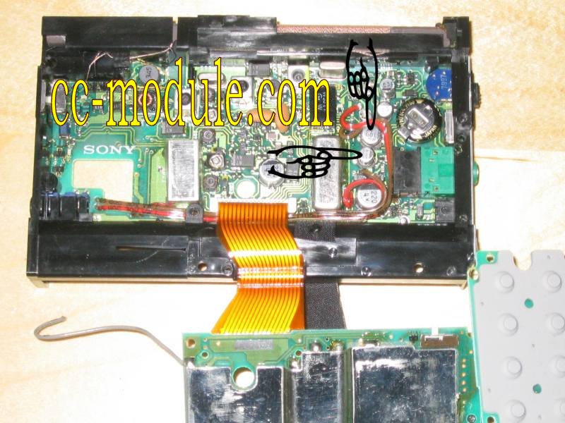
Heat
up the solder points left and right of the SMD-capacitors and remove
the capacitors.
Remember the polarity! The view of the printed circuit board is
switched by 180°
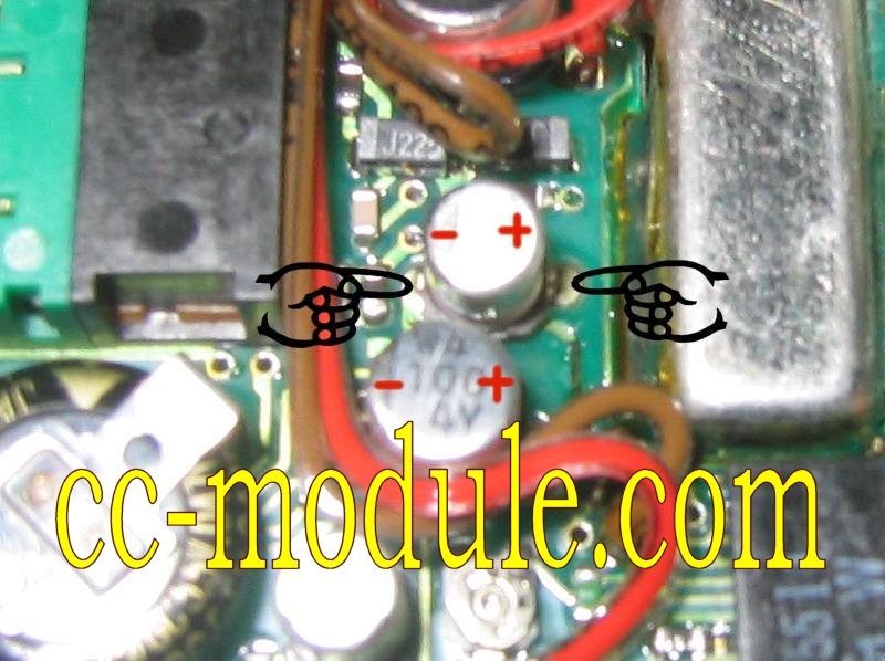 Solder
the new capacitors. Remember the polarity!
It is easier to solder the capacitors in upright position. Bend them
afterwards.
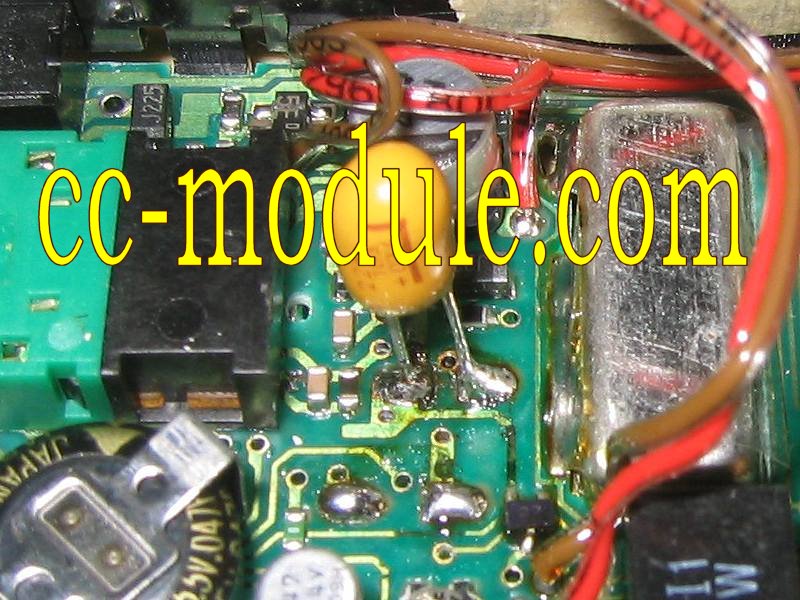
After soldering run the cables in original position.
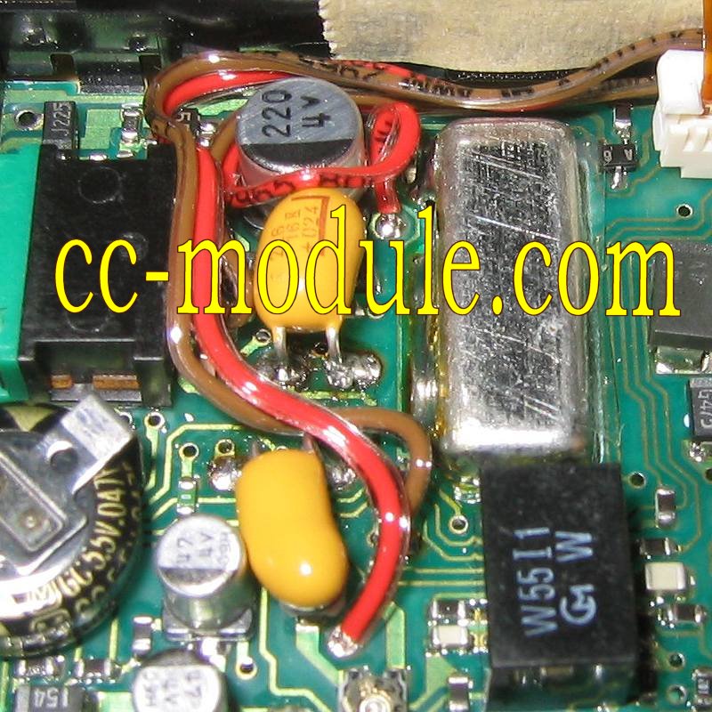
Once
you opened the SW1 it makes sense to change the dark green LED
to a new super bright white LED. Remember the
polarity!
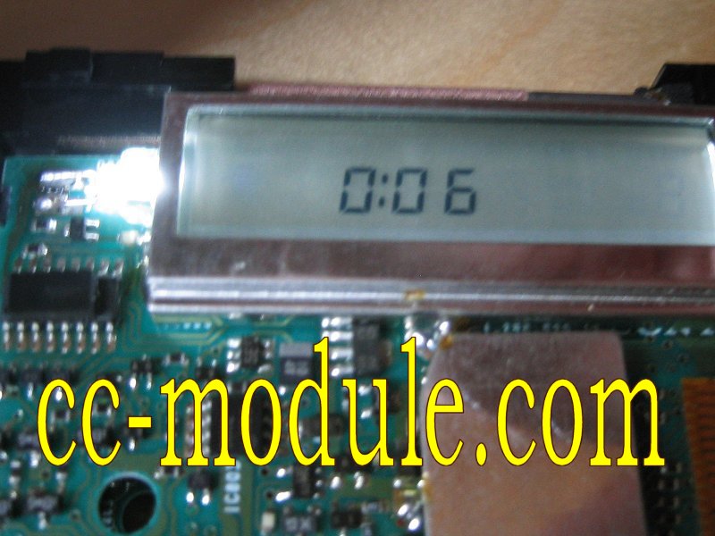
Assemble all parts and be careful with the switches ON/OFF, LIGHT and TONE.
Get this instruction as a PDF-File for a nominal charge.
You need a helping hand for the repair?
Don't hesitate to contact me for shipping the spare parts.

You
could repair your SW1?
Donations welcome.

Letter to the editor:
Hello. With your
instruction I easily repaired my receiver ..... Thank you very
much for your solution. Anatoly, Moscow, Russia
---
I could just fix my
veteran Sony SW1 based on your guide - after a few years
of inoperation. Excellent piece of work - Thanks. Danke.
---
Hi, thanks for the clear
instruction & pictures; a small donation will follow.
I'm a novice to electronical work, but can suggest 2 things on the
SW1
instructions.
1.) The 3 screews on the initial back opening; should note that 1 is
a machined
thread and the other is a wood thread for re-assembly.
(Note: Some SW1 have two machined thread screews! Depends on creation
date)
2.) More importantly - when soldering in the new caps I spent a lot
of time trying to
discern exactly where they go by studying your photos. You see. I was
looking for
holes from where the old ones came from, but in reality, its just an
open space or
field where they go, at least I thought so and it seems to work fine
now. (Note:
SMD based motherboards have no holes for fixation) Thanks
Danny.
---